ILX Connection — Complete Documentation
1Introduction
ILX Connection is a Windows desktop application for structural steel connection design. Build a connection from standard W-shape sections, plates, bolts, and welds in a real-time 3D viewport, then run a Component-Based Finite Element Method (CBFEM) analysis with AISC 360-16 design checks and a printable PDF report — all in one tool, with no FEA pre/post-processing software required.
Why CBFEM?
Traditional connection design relies on simplified analytical models that can miss interaction effects between components. CBFEM builds a shell-element FEA model of every plate and member stub, applies the actual load vector, and checks each component to the AISC limit states directly from stress and strain results.
Recommended First Workflow
- Define members and verify section properties.
- Add plates, bolts, welds, stiffeners, or gussets.
- Confirm member orientations and connection eccentricities.
- Apply forces and moments from the structural model or project calculations.
- Run CBFEM and review mesh quality warnings.
- Review AISC check utilization, stress contours, deformed shape, and governing components.
- Modify geometry and repeat until checks pass with appropriate engineering margin.
- Generate the final report and save with the issued calculation package.
2System Requirements
| Requirement | Minimum | Recommended |
|---|---|---|
| OS | Windows 10 (64-bit) | Windows 11 |
| CPU | 4-core | 8-core |
| RAM | 8 GB | 16 GB |
| GPU | OpenGL 3.3 compatible | Dedicated GPU, 4 GB VRAM |
| Storage | 1 GB free | 5 GB |
| Display | 1920 × 1080 | 2560 × 1440 |
OpenGL 3.3 is required for the 3D viewport. Most GPUs manufactured after 2012 support it. Integrated graphics (Intel HD/UHD, AMD APU) are supported at reduced performance.
3Installation & Licensing
Installation
- Download
ILX-Connections-Setup.exefrom the ILX Studio website. - Run the installer. A Start Menu entry is registered.
- On first launch, sign in with your ILX Studio account credentials to activate your seat.
Seat Management
Your seat is tied to your ILX Studio account. Sign in on one machine at a time. Sign out via File → Account → Sign Out to release your seat for use on another machine.
Updates
File → Check for Updates — updates are cryptographically signed and verified before installation.
4Getting Started
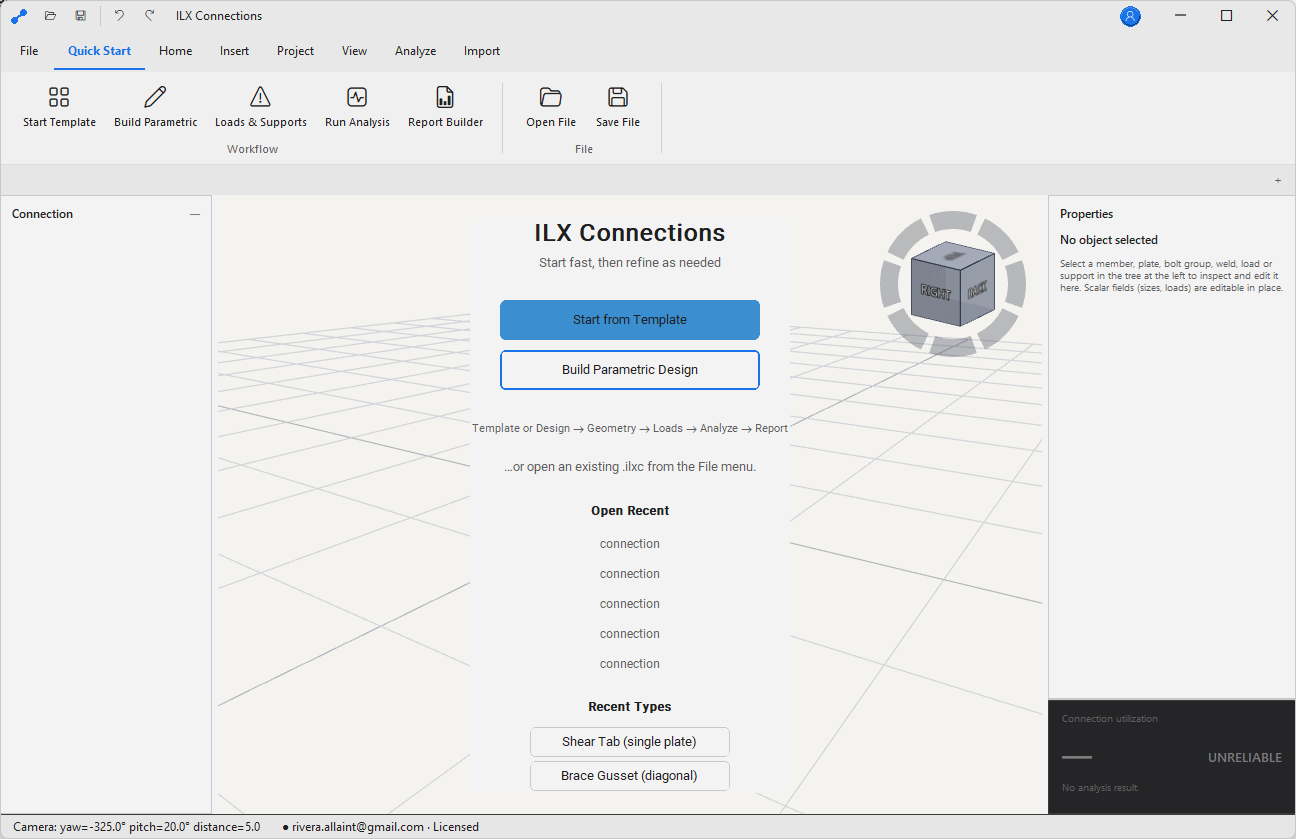
Creating a New Connection Model
- Click New Connection on the Start page, or press Ctrl+N.
- A blank 3D workspace opens with the default coordinate system (X = right, Y = up, Z = toward viewer).
- Add the primary member: Members → Add Column.
- Add the secondary member: Members → Add Beam.
- Add the connection element: Connections → Add Plate / Bolts / Welds.
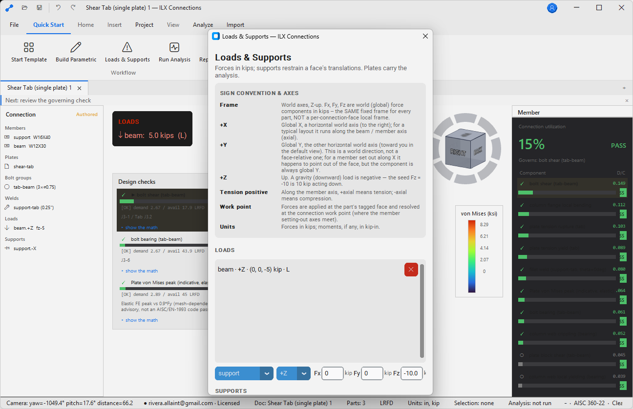
- Apply loads: Loads → Applied Forces.
- Run: Analysis → Run CBFEM.
Opening an Existing Project
Ctrl+O or drag a .ilxc project file onto the application. ILX Structures reaction files (.ilxr) can also be opened — loads are imported directly.
5The Interface
Ribbon Tabs
| Tab | Contents |
|---|---|
| Home | New, open, save, undo/redo |
| Members | Add/edit column, beam, brace members |
| Connections | Add plates, bolts, welds, gussets, stiffeners |
| Loads | Applied forces and moments at each member end |
| Analysis | Run CBFEM, run self-test, view mesh |
| Results | AISC check tables, stress contours, deformation |
| Render | Photorealistic PBR render settings and export |
| Report | Generate PDF, preview |
| Settings | Units, materials, section catalog, display |
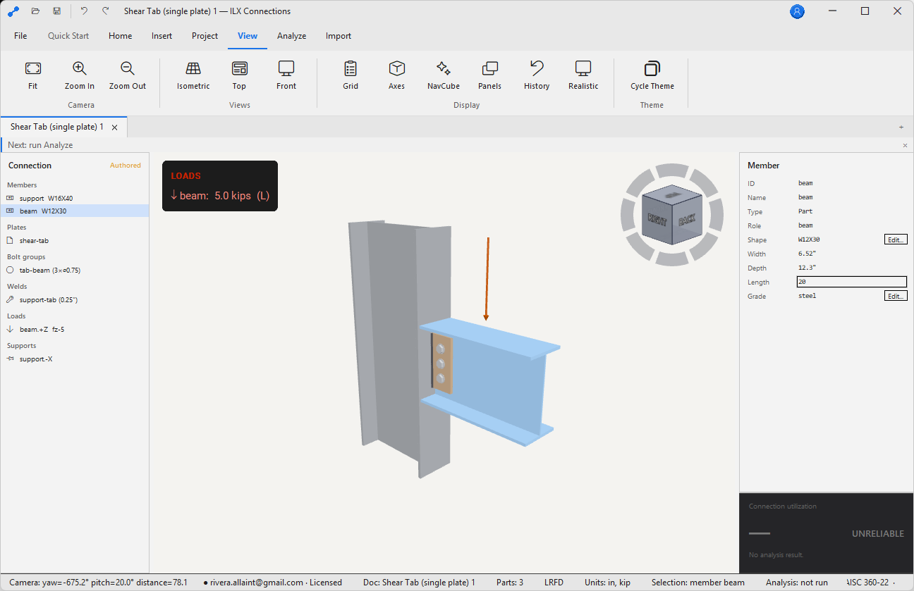
3D Viewport
The central viewport uses an orbit camera — click and drag to orbit, middle-click drag to pan, scroll wheel to zoom. The NavCube in the upper-right lets you snap to standard views (top, front, right, isometric) with a single click.
Properties Panel
Selecting any element in the viewport opens its properties in the right-side panel. All properties can be edited directly; the viewport updates in real time.
6Building a Connection
ILX Connection uses a parametric connection model — define geometry by setting parameters and the model updates automatically. No manual geometry drawing required.
Connection Types Supported
| Connection Type | Notes |
|---|---|
| Shear tab (single plate) | Simple shear, standard and extended |
| Double-angle | Bolted or welded to web |
| End plate (flush and extended) | Moment connection; 4-bolt and 8-bolt patterns |
| Flange plate | Moment connection with welded flange plates |
| Gusset plate (brace) | Concentric and eccentric bracing |
| Column base plate | With anchor rods; axial + moment + shear |
| Seated beam connection | Clip angle or seat plate |
| Splice (beam or column) | Bolted or welded |
7Members — Columns & Beams
Adding a W-Shape Member
- Go to Members → Add Column (or Add Beam).
- Click the Section field to open the Shape Selector.
- Type a section name (e.g.
W14x99) or browse by depth and weight range. - Set Material: A992 (Fy = 50 ksi) is the default for hot-rolled W-shapes.
- Set Orientation: rotation about the member axis, in degrees.
Material Properties (Default A992)
| Property | Default | Notes |
|---|---|---|
| Fy | 50 ksi | Minimum yield strength |
| Fu | 65 ksi | Minimum tensile strength |
| E | 29,000 ksi | Modulus of elasticity |
| G | 11,200 ksi | Shear modulus |
Custom materials can be defined in Settings → Materials. The full AISC shapes database may require an appropriate license; custom shapes can be entered manually.
8Plates, Bolts & Welds
Plates
Add plates via Connections → Add Plate. Specify dimensions, material (A36 default, Fy = 36 ksi), position relative to the primary member, and attachment method (bolted, welded, or both). Plates are modeled as MITC4 shell elements in the CBFEM mesh.
Bolt Groups
Add bolt groups via Connections → Add Bolt Group. Specify bolt diameter (¾" – 1¼"), grade (A325 or A490), thread condition (X or N), hole type (STD, OVS, SSLT, LSLT), row × column pattern with pitch and gauge, and pretension level (snug-tight or fully pretensioned).
Welds
Add welds via Connections → Add Weld. Choose fillet or CJP (complete joint penetration) type, electrode (E70XX default, Fu = 70 ksi), weld size, and select the plate edges to weld in the viewport.
9Running the CBFEM Analysis
How CBFEM Works
Clicking Analysis → Run CBFEM meshes each plate and member stub as MITC4 shell elements, assembles the global stiffness matrix, applies the specified load vector, solves the linear static problem (with optional GMNA for buckling-sensitive connections), extracts stresses and strains, then evaluates AISC 360-16 Chapter J checks.
Solve Time
Most connections solve in under 10 seconds. Large gusset plates or heavily bolted connections with fine meshes may take 30–60 seconds.
Self-Test
Analysis → Run Self-Test runs benchmark problems with known analytical solutions and verifies the FEA engine is within tolerance. Run this after installation and after any update.
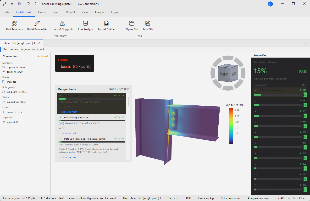
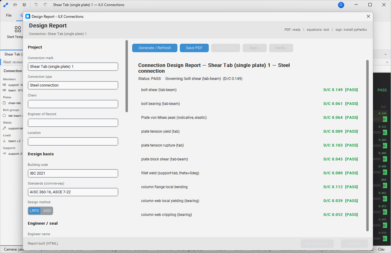
10AISC 360 Design Checks
The Results tab shows a table of all AISC 360-16 limit-state checks. Each row includes demand, capacity (φRn or Rn/Ω), utilization (must be ≤ 1.0), status (✓/×), and the AISC clause reference.
Checks Performed
| Limit State | AISC 360-16 |
|---|---|
| Bolt shear | J3.6 |
| Bolt bearing on plate | J3.10 |
| Bolt bearing on member web/flange | J3.10 |
| Bolt slip (slip-critical) | J3.8 |
| Weld shear — fillet welds | J2.4 |
| Weld fusion — CJP welds | J2.1 |
| Plate gross-section yielding | J4.1 |
| Plate net-section rupture | J4.1 |
| Block shear rupture | J4.3 |
| Local buckling — plate slenderness | — |
| Column web local yielding and crippling | J10.2, J10.3 |
| Column flange bending (moment connections) | J10.6 |
LRFD vs. ASD
Switch between LRFD and ASD in Settings → Design Method. The check table and report update immediately.
113D Viewport
Navigation
| Action | Control |
|---|---|
| Orbit | Left-click drag |
| Pan | Middle-click drag |
| Zoom | Scroll wheel |
| Snap to view | Click a NavCube face |
| Fit all | F or double-click NavCube |
| Select element | Left-click |
| Multi-select | Shift + left-click |
Display Modes
- Wireframe — edges only, fastest
- Solid shaded — flat shading, opaque
- Solid + edges — shaded with edges highlighted
- Stress contours — von Mises or principal stress (available after solving)
- Deformed shape — amplified deformation overlay (scale factor adjustable)
12Photorealistic Render
ILX Connection includes a PBR (Physically Based Rendering) render path built on the same OpenGL viewport — no separate render engine or export required. Enable with Render → Enable PBR Render.
Render Presets
| Preset | Description |
|---|---|
| Shop floor | Industrial lighting, concrete floor |
| White studio | Neutral white environment for report images |
| Outdoor | Sky HDR, directional sun |
| Custom | Load your own HDR environment map |
Exporting a Render
Render → Export Image — PNG or JPEG, up to 4K resolution. Use for report cover images, presentation slides, shop drawing illustrations, and RFI attachments.
13Reports
Report → Generate PDF produces a multi-section PDF: cover page, connection summary, input summary, AISC check table (with full derivation and substituted values), FEA result images, and the PE-seal block — activated only when all checks pass.
Report Settings
Settings → Report — configure firm name, engineer name, logo (PNG ≤ 300 × 150 px), design method (LRFD/ASD), and whether to include FEA stress contour images.
14Settings
| Setting | Location | Options |
|---|---|---|
| Units | Settings → Units | US Customary / SI |
| Design method | Settings → Design Method | LRFD / ASD |
| Theme | Settings → Display → Theme | Dark / Light / High-Contrast |
| Section catalog | Settings → Section Catalog | Built-in starter / AISC full |
| Default bolt grade | Settings → Defaults → Bolts | A325 / A490 |
| Default electrode | Settings → Defaults → Welds | E70XX / E80XX |
| Mesh density | Settings → Analysis → Mesh | Coarse / Normal / Fine / Custom |
| Autosave | Settings → Files | Interval in minutes |
15Troubleshooting
Viewport Shows a Black Screen
Verify your GPU supports OpenGL 3.3. Update graphics drivers from the GPU manufacturer. As a fallback, enable Settings → Display → Software Renderer.
Analysis Fails with “Stiffness Matrix Singular”
A component is not connected to any other. Check that all plates are bolted or welded to at least one member or plate.
“Section Not Found in Catalog”
Enter dimensions manually: Members → Properties → Section → Manual Entry. The built-in starter catalog covers the most common W-shapes.
Report PDF is Blank or Corrupt
Ensure at least 200 MB of free space in your %TEMP% folder. Try pointing the output to a local folder: File → Settings → Report → Output Directory.
Self-Test Fails
Contact support@ilxstudio.com with the self-test log from %LOCALAPPDATA%\ILX Studio\Connections\Logs\selftest.log.
A–HAppendices
A. Manual Conventions
| Convention | Meaning |
|---|---|
| Bold text | Button, ribbon tab, menu item, panel name, or UI label |
Monospace | Command, file extension, keyboard shortcut, path, or literal value |
| File → Open | Menu path or ribbon navigation sequence |
| ✓ / ✗ / ⚠ | Pass, fail, and warning status indicators |
B. File Management
Store active projects in a version-controlled or backed-up project folder. Use clear filenames with project number, discipline, revision, and date. Keep exported PDFs separate from editable native project files (.ilxc).
C. Validation & Professional Review
ILX Connection assists qualified users; it does not replace professional judgment. The responsible engineer must verify all inputs, load paths, boundary conditions, connection geometry, and final reports before issuance.
D. Accessibility
Supports Dark, Light, and High-Contrast themes. Increase UI text scale in Settings → Display. Use keyboard shortcuts for repeated commands.
E. Support & Logs
Include product name and version, Windows version, project file (if permitted), steps to reproduce, screenshots, and log files from %LOCALAPPDATA%\ILX Studio\Connections\Logs\ when contacting support@ilxstudio.com.
F. Glossary
| Term | Meaning |
|---|---|
| CBFEM | Component-Based Finite Element Method — shell FEA of connection components with AISC limit-state checks. |
| DCR | Demand-to-Capacity Ratio; values above 1.0 indicate failure for strength checks. |
| LRFD | Load and Resistance Factor Design — strength design with load and resistance factors (φ). |
| ASD | Allowable Stress Design — service-level design with safety factors (Ω). |
| MITC4 | Mixed Interpolation of Tensorial Components, 4-node — the shell element formulation used for CBFEM meshing. |
G. Revision History
| Version | Date | Notes |
|---|---|---|
| 1.0 | 2026 | Initial manual draft. |
| 1.1 | 2026 | Expanded professional-use guidance, QA, accessibility, and glossary content. |
H. Steel Connection Review Checklist
- Member sizes, materials, orientations, and connection geometry.
- Load source, sign convention, and whether loads are ASD or LRFD.
- Bolt grade, diameter, hole type, thread condition, pretension, and slip-critical assumptions.
- Weld size, electrode, effective length, and access for fabrication/inspection.
- Plate thickness, edge distances, spacing, and constructability.
- Mesh warnings, stress concentrations, and governing AISC checks.
- Report includes all required load combinations and governing components.